In this article, which is the first in a four-part JumboSwitch education series with corresponding videos, we take a closer look at the first JumboSwitch® troubleshooting feature, something we like to call “troubleshooting at a glance” using the JumboSwitch’s built-in, color-coded LED indicators.
TC Communications’ JumboSwitch® offers four key troubleshooting, monitoring, and network management features:
- “Troubleshooting at a glance” using LED units on the front panel
- The built-in graphical user interface
- Our TCView® network management system
- SNMP (Simple Network Management Protocol) integration with third-party network management systems
In the following discussion, we use the TC3846-6 as an example. The LEDs are similar, but not identical on the other JumboSwitch cards. Please refer to the relevant manual for specifics.
Alarm Status LED
We refer to the JumboSwitch’s alarm LEDs as troubleshooting at a glance because it is easy to determine if a fault has occurred just by looking at the LEDs on the card.
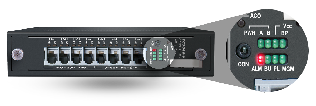
The Alarm Status LED is present on all JumboSwitch cards and is the only red LED on the front panel, making it easy to spot. It is located directly above the eight ports 600 O audio and dry contact ports on the front panel (to the right when viewed horizontally). See below:
There are three main ways the alarm LED communicates troubleshooting status:
- If the alarm light is ON (solid red), an alarm has been triggered and is present on that card.
- If the alarm light is FLASHING, there was an alarm that is now cleared.
- If the alarm light is OFF (not lit), no alarm has been triggered.
Even when multiple JumboSwitch cards are configured, initial troubleshooting is immediate, as the eye is drawn to any red alarm LEDs, which signify operational problems.
You can then take a closer look at the other types of LEDs and use the graphical user interface (GUI) or TCView network management system to determine what the fault is and how to rectify it.
Power and Voltage Status LEDs
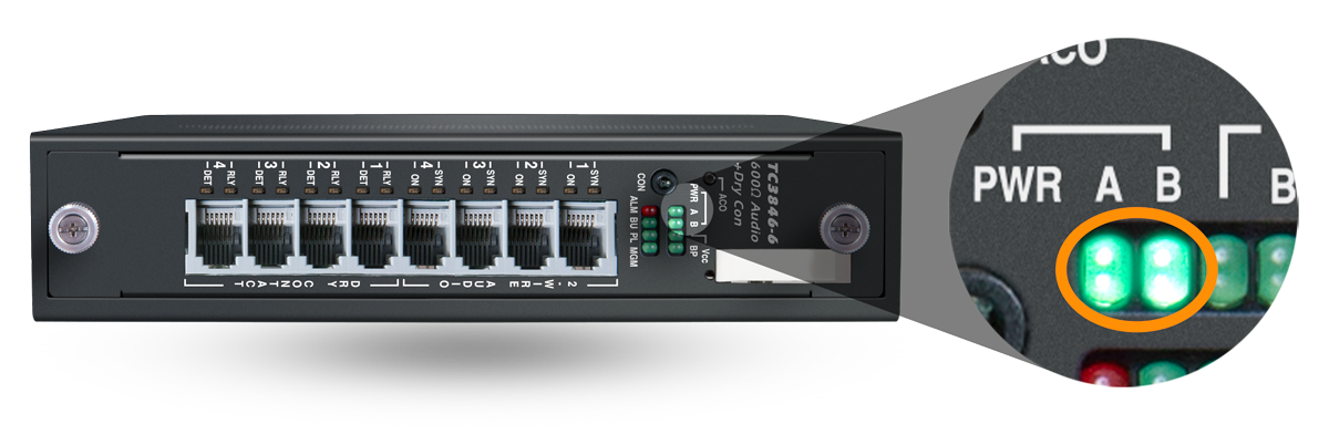
Directly above the alarm status LED (to the right when viewed horizontally), there are three Power Status and Voltage Status LEDs that provide a quick view of whether power is being provided to the card. These consist of two A/B power LEDs on the left and one Vcc (voltage) status LED next to those. See below:
These LEDs indicate power and voltage status as follows:
Power Status LEDs
The power status LEDs shows if power from the two power supplies is present.
- If the A/B power LEDs are ON (solid green), power is being supplied. No action is needed.
- If either A/B power LED is OFF (not lit), power is not being supplied from that power source.
- Only one LED must be on to be operational; however, an LED being off indicates one of the power sources has been cut off.
- When an A/B power LED is off, check your system’s fuses, power supplies, power sources, and power cabling.
Voltage Status LED
The voltage status LED shows if power is reaching the interface card correctly.
- If the Vcc status LED is ON (solid green), the operating voltage is good (Power A and/or B supplying power). No action is needed.
- If the Vcc status LED is OFF (not lit), the incorrect operating voltage is being supplied. In this case, try the following:
- Ensure that the card is plugged into the chassis completely.
- Visually inspect the back connector pins.
Buffer Underrun and Packet Loss LEDs
Directly below these power/voltage LEDs (to the left when viewed horizontally) and adjacent to the red alarm LED are the Buffer Underrun (BU) and Packet Loss (PL) LEDs. See below:
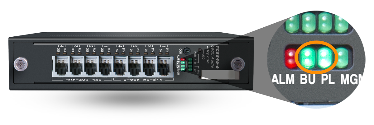
Unlike the power and voltage status LEDs, these LEDs being on (lit) indicate a problem status instead of correct operation, and in conjunction with either of these LEDs being on, the alarm LED will also turn on. They work as follows:
Buffer Underrun LED
- If the BU LED is ON (solid green), the Ethernet network has high PDV (packet delay variation) or other issues. In this case, try the following:
- Troubleshoot the Ethernet network for bandwidth and delay issues.
- Verify QoS and priority settings from end to end.
- If the BU LED is OFF (not lit), the Ethernet network PDV is within specified tolerance. No action is needed.
Packet Loss LED
- If the PL LED is ON (solid green), the Ethernet network is experiencing packet loss or other issues. In this case, try the following:
- Troubleshoot the Ethernet network for bandwidth and loss issues.
- Verify QoS and priority settings from end to end.
- If the PL LED is OFF (not lit), there is no packet loss within the Ethernet network. No action is needed.
Backplane and Management Status LEDs
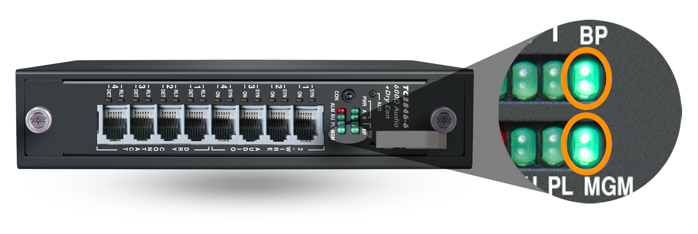
On the rightmost side of both of these rows of LEDs, there are two additional LEDs: the Backplane (BP) LED in the upper row and the Management Status (MGM) LED in the bottom row. See below:
These two LEDs indicate status as follows:
Backplane or Back Port Status LED
- If the BP status LED is ON (solid green), either the card is connected to the backplane or there is connection on the back Ethernet port. No action is needed.
- If the BP status LED is FLASHING, link activity is detected. No action is needed.
- If the BP status LED is OFF (not lit), there is no connection to the backplane or no connection on the back Ethernet port. In this case, try the following:
- Ensure the card is plugged into the chassis completely.
- Visually inspect the back connector pins.
- Check the Ethernet cable and connection.
Management Status LED
- If the MGM status LED is ON (solid green), the card has finished booting and the card is recognized. No action is needed.
- If the MGM status LED is FLASHING, the card is booting or initializing. If several minutes have passed, check the CLI for boot errors.
- If the MGM status LED is OFF (not lit), the card has finished booting and the card is running as a standalone, and being off is standard. No action is needed.
Port Status LEDs
Analog Port LEDs
Located to the left of the four 600 O audio ports on the front panel (when viewed vertically), there are two types of Analog status LEDs, which are stacked on top of one another: the Synchronization (SYNC) LEDs on top and the analog signal LEDs (signified as “ON”) on the bottom. See below:
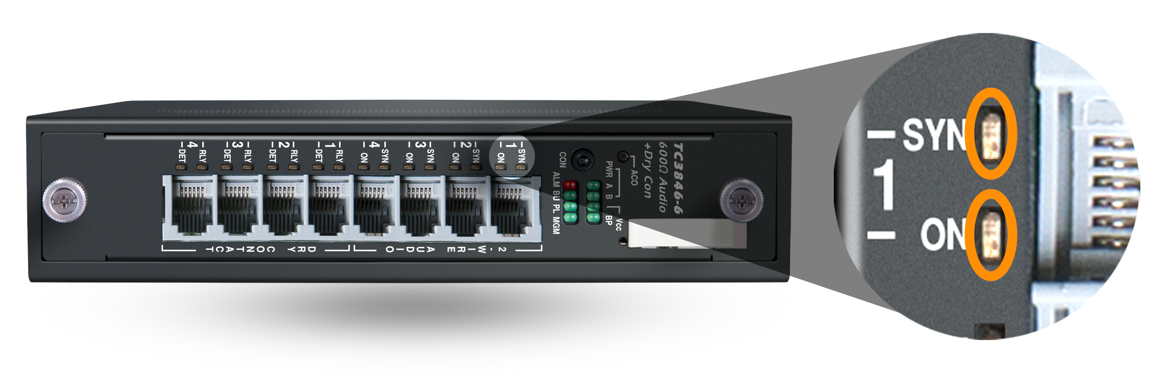
These two types of LEDs indicate the following:
Synchronization LEDs
- If the SYNC LED is ON (solid green), the audio port is synced with the remote port (operational).
- If the SYNC LED is FLASHING, the audio port is not synced with the remote port (inoperative or the IP setup is incorrect).
- If the SYNC LED is OFF (not lit), the audio port has been disabled.
Analog Signal LEDs
- If the ON LED is ON (solid green), the analog signal is detected.
- If the ON LED is OFF (not lit), the analog signal is not detected.
Dry Contact Port LEDs
Below the Analog Port LEDs and to the left of the dry contact ports, there are two types of LEDs for the relays (RLY) and dry contact detection (DET). See below:
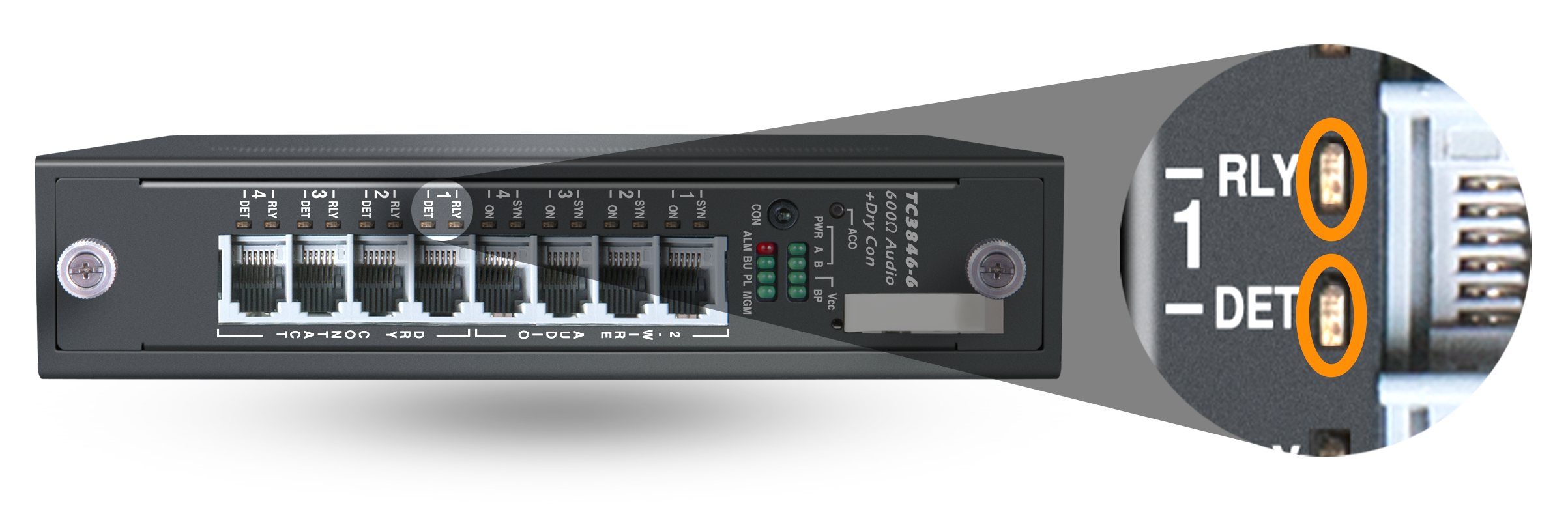
These two types of LEDs indicate the following:
Relay Status LEDs
- If the RLY LED is OFF (not lit), the relay is open.
- If the RLY LED is ON (solid green), the relay is closed.
Dry Contact Detection LEDs
- If the DET LED is OFF (not lit), no closure is detected.
- If the DET LED is ON (solid green), dry contact is detected.
Ultimately, these LED indicators have been designed so that you can recognize when there is an issue immediately and begin further troubleshooting. Any alarms that are raised will be recorded in the alarm log, which can be accessed in the JumboSwitch product’s graphical user interface, which will be the next topic in this JumboSwitch education series.
To read other JumboSwitch articles from this series, visit the JumboSwitch Monitoring Series page.
Interested in similar content? Subscribe to our mailing list.