1996 - Canadian Bridge Traffic System Requires a Self-Healing Ring
Self-Healing Ring Fiber Multiplexers Provide Reliable Data Transport For Canadian Bridge Traffic System
Opened in 1997, the 12.9 kilometer Confederation Bridge that joins Borden-Carleton, Prince Edward Island and Cape Jourimain, New-Brunswick is the longest bridge over ice-covered waters in the world. The Bridge carries one lane of traffic each way and takes approximately 10 minutes to cross at the normal speed limit of 80 kmph.
“Normal” speeds, however, are often wishful thinking in Canada’s Maritime Provinces. Prince Edward Island averages about 10 feet of snow a year, and the average daily maximum temperature is below freezing December through February. Driving can even be hazardous even during the so-called “good weather” months.
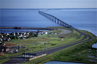
Opened in 1997, the Confederation Bridge joins Borden-Carleton, Prince Edward Island and Cape Jourimain, New Brunswick.
To help motorists drive over the bridge as safely as possible, in all types of weather, Bridge planners included a variety of important traffic-related equipment:
- Changeable Message Signs at each end of the Bridge
- Thirty-four Traffic signal units throughout the Bridge
- Emergency Telephones every 750 meters
- Weather Monitoring Station
- 17 Surveillance cameras
To manage and integrate the functionality of this equipment, Bridge planners included a sophisticated Traffic Management System (TMS). The primary goal of the TMS is to monitor traffic and roadway conditions and provide current traffic information and warnings.
The TMS consists of several distinct sub-systems (e.g. Traffic Signs, Traffic Signals and Roadway Lighting). All sub-systems are coordinated by the Management Center in the Bridge Operations Building (BOB) located adjacent to the toll plaza.
The core of the TMS is the communications sub-system. It transports data, video and voice signals between the various sub-system field devices (e.g. controllers) and the BOB.
Data Communications Network
Realizing the critical nature of the communications sub-system, Bridge planners took significant precautions to insure maximum reliability. One of these precautions called for installing a 27 kilometer fiber optic ring with self-healing function multi-drop fiber optic multiplexers for transporting data between the computers at the BOB and the various controllers on the Bridge.
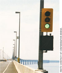
Thirty-four traffic signal units are located throughout the Bridge.
The fiber optic ring uses four fibers, two East and two West, and travels in counter-rotating directions. It consists of two data paths, Ring A and Ring B, with each data path running in an opposite direction to the other. ( See Figure 1).
Twenty-three 8-channel fiber optic multiplexers transport data from the computers at the Bridge Operations Administration Building (BOB) to the controllers for traffic signs, signals, roadway lighting, call box alarms, a vehicle counting station, and a weather monitoring station. The “Master” multiplexer is located in the BOB. (See Figure 2).
Technical requirements for the self-healing ring multiplexers were stringent. Specifications included:
- "...dual redundant, self-healing ring configuration."
- "Fault tolerance and automatic switching shall prevent any fibre fault or failed multiplexer from affecting the data flow on the aggregate ring."
- "In the event of a fiber fault or multiplexer failure, communications shall be automatically re-routed around the failed area by way of the redundant ring."
- "...a minimum of 8 independent, full-duplex, asynchronous EIA data channels…."
Self-Healing Multiplexers
After comprehensive testing and analysis, Bridge Planners chose Model TC2800 multiplexers from TC Communications in Irvine California.
According to Ken Edwards, Manager, Information Systems for Confederation Bridge, the systems integrator in charge of planning this portion of the network was told to find a communications system that was “robust, dependable and ‘off the shelf.’”
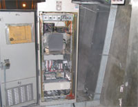
Environmental-controlled equipment cabinets are housed inside the box-beam sections of the Bridge at 750 meter intervals.
“I think the multiplexers have met this criteria… the TC2800s have worked flawlessly since they were installed in 1997,” said Ken.
The TC2800’s were especially efficient because all channels are totally independent. Because of this feature, the six channels in use are connected to three different operating systems: two Windows-based and one UNIX-based.
Each of the channels are polled every 20 seconds. If a change is made to the state of a device on the channel, the information is sent to the device immediately. All channels, except channel 8, communicate at 9600 baud. Channel 8 communicates at 1200 baud.
One of the two spare channels may be used in the future to monitor the current for the Cathodic Protection System (CPS). The CPS is used to protect the steel ice shields that were originally installed on the extreme west and east sides of the Bridge.
(Note: Cathodic protection reduces underwater corrosion of metal parts. When two dissimilar metals are placed the water, they create a battery. To compensate for this an impressed current system is used to pump electricity into the water from an inert, non-corrodible anode. The current flow can be regulated to protect the desired metal parts…in this case the steel ice shields).
Automatic Switchovers
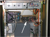
Eight-Channel Model TC2800 Fiber Optic Multiplexer (middle right).
According to Ken, the self-healing ring system has had a few instances that have triggered automatic switchovers since it was cut over in May of 1997. To date, these instances have been related to power interruptions or periodic tests. For example, a power failure to one TC2800 multiplexer will cause the upstream and downstream units to go into a self-healing ring condition. None of the switchovers have been related to cable breaks or equipment failures.
“In every switchover condition, the self-healing ring function has worked as it was designed...the muxes have proven to be extremely reliable,” Ken said. Ken also referred to a “vicious lightning storm” that battered the bridge last summer. He was pleased to note that “virtually all of the communications equipment, including the fiber multiplexers, continued to function properly…the only casualty was a RS- 232/485 converter.”
Installation
To provide a stable climatic environment, equipment cabinets are used to house the various controllers and communications field equipment, including the fiber optic multiplexer “slave” units. The equipment cabinets, located 750 meters apart are installed inside the box-beam sections of the bridge. The cabinets are weather proof and conform to pertinent NEMA specifications. Heaters and fans inside the cabinets help maintain a constant temperature of 60 degrees.
According to Ken “the fiber muxes were very easy to install”; however, he noted that he had to troubleshoot a communications problem unrelated to the multiplexers.
“Due to the hectic work schedules to get the bridge open on schedule, the fiber optic splices at each call box were not tested. We developed a repetitive communication problem and were able to isolate it to a particular section of the bridge. We had the installer go back and test the fiber optic splices and a couple splices were found to be deficient. After correcting these, communications have been excellent.”
8-Channel Designation on TC2801
- PLC for variable speed signs, roadway lighting, call box alarms & traffic signals.
- PLC for variable speed signs, roadway lighting, call box alarms & traffic signals.
- Interchangeable traffic signs at each end of the bridge.
- Vehicle counting station at the east end of the bridge
- Weather monitoring devices for wind snow and rain.
- Spare channel. (Not Used)
- Spare channel. (Not Used)
- Traffic signals at the west end of the bridge.
TMS Overview
TMS management is performed by the Bridge Management Computer System. It processes and logs incoming data and suggests appropriate responses to detected incidents via a graphical user interface (GUI) with a real-time TMS status display. The Traffic Management System also includes full video surveillance, emergency call boxes and continuous weather monitoring.
Video surveillance of the bridge and its approaches is provided by pole-mounted closed circuit television cameras located at 750m intervals along the south side of the bridge.
Emergency call boxes are located at 750m intervals along the north side of the Bridge. These call boxes enable motorists to contact the operator in the Bridge Control Center (BCC) directly. Call boxes also include a fire extinguisher and an external emergency alarm pushbutton (button sends alarm message to BCC).
Continuous weather monitoring provides the BCC with real-time information on the weather conditions such as wind speed, wind direction, air temperature, road temperature, humidity, dew point and rate of precipitation. The Bridge’s electrical system, including traffic lights, street lights and the toll system, is supported by an uninterruptible power supply and a back-up electrical generator. There are 34 traffic signal units on the Bridge. Under normal conditions all signals will be green.
The Changeable Message Signs, located at each end of the Bridge, transmit messages to the driver about conditions on the Bridge.
Readers can go to www.confederationbridge.com for more information on the Confederation Bridge.
Self-Healing Ring Issues
It is important to note that all Self-Healing Ring methodologies are not alike. Vendor offerings vary greatly in terms of function, features and sophistication. The term "self-healing" likely means something different to a vendor’s advertising copywriter than it does to the engineering supervisor responsible for a given network.
For example, some vendors offer a self-healing scheme that doesn't separate broadcast and receive channels. As a result, activating the self-healing function can cause these channels to interfere with each other (often referred to as “echo effect”).
Other vendor offerings can detect cable breakage only at the receiving side. Unless the device can detect failures at the transmit side, there is no way to know if the next device is receiving the signal.
Modern self-healing networks often require multiplechannel communications rather than relying on a single channel. Multi-channel communications can be used for controls or as additional communication channels and offer several benefits. For example, it can enable a Slave unit to contact the Master unit without waiting for the normal polling sequence or cut down overall network polling times by using two Host ports.
Large Multi-Drop networks, networks with several hundred Slave units, can require 10 to 30 minutes to complete a polling cycle. Given that a lot of unpleasant things can happen in a short amount of time, it is extremely important for Slave units to have the ability to immediately contact the Master.
With a single channel, a Slave waiting to broadcast an emergency signal must wait until it is polled by the Master. With an extra channel to pass RTS/CTS controls, any Slave can raise RTS and contact the Master directly.
Communications engineers often face the dilemma of how to link process control systems in various manufacturing, utility or traffic control environments. Certainly, each application presents its own uniqueness; however, the connectivity issues are similar—the communications must be real-time, reliable and self-monitoring.
TC Communications addresses process control connectivity issues with a variety of reliable products that include Multi-Drop Modems/Multiplexers, Ethernet and Broadcast and Receive devices. Together or singly, these products provide effective and economical solutions.