1997 - Oregon Utility Believes in TC's Self Healing Fiber Ring Network
Oregon Utility Boosts Network Reliability with Multi-Drop Fiber Optic Modems
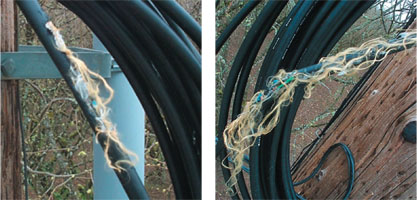
Thanks to a hungry (or angry) squirrel with sharp teeth and strong jaws, the Springfield Utility Board (SUB) found that its new self-healing ring fiber optic communications network worked. It worked so well, in fact, that several days went by before they realized that the cable had been severed in one of the fiber optic rings.
“We cut the system over successfully on Friday,” said Tom Weller, Substation & Metering Engineer,” and noticed on Monday that a switchover to the backup ring had occurred. We had suspected a bad splice or jumper cable and were more than a little surprised when an Optical Time Domain Reflectometer (OTDR) reading showed a break in the middle.
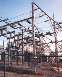
“We sent out a technician to investigate, and sure enough, several feet of the cable had literally been chewed to pieces by what we assume to be a squirrel. (See photographs on this page). The damage to the cable was remarkable. But we found out the selfhealing ring worked.”
Search for Reliability
Spurred by a need for more reliability, SUB began looking into installing a new communications network to link its substations with the Master Communications Center in late 1996. It would continue to use its existing SCADA software.
At that point, Springfield communicated with its substations over leased telephone lines. Because of the leased line’s vulnerability to ground faults, reliability was a constant concern, according to Tom. “When it rained, the Mt. Vernon substation leased line went down like a bowling pin and it took the total communications network with it,” Tom explained. “This substation includes some old underground lines installed in the 60’s and they would always ground out when it rained. With 48 average inches of rainfall per year this was a continuing concern. This situation was especially stressful because this substation is a delivery point from Bonneville Power.
“In some instances, with the leased line system, we would be down for two or three days. That made scheduling power a real guessing game.”
Springfield’s technicians tried several stop-gap efforts to keep the old system functional. For example, to prevent one node failure from disabling the entire network, Springfield technicians split the bridged network into two and had the bridge location brought back to the Master Station. This fix helped the overall situation, but still only maintained communications to one-half of the substations when a fault occurred. The faulted line was then removed by flipping a toggle switch and allowing normal communications to resume to the remaining RTU’s while waiting for the Telephone Company to repair the faulted line.
The Proposal
Once Springfield made the decision to install a new communications network, the project moved quickly, according to Bob Linahan, Director of Electric Engineering & Operations.
“We’re (Springfield) not afraid of doing something new,” Bob said, “We are willing to make a decision and go do it.”
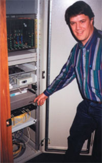
Tom Weller, Substation and Metering Engineer, points to equipment rack with TC2100 Multi-Drop Fiber Modem.
According to Tom Weller, Springfield looked at several communication network alternatives, including other telephone systems, but soon focused on using fiber optic modems in a self-healing ring configuration.
“After talking to several other Utilities and contacting a few vendors, it became obvious that this option would give us the benefits we were looking for, especially reliability and future expansion,” Tom said.
Using fiber optics would eliminate ground fault problems and the self-healing ring would insure system integrity by automatically re-routing communications in the event of a cable or device failure. Furthermore, the fiber modems would include anti-streaming/antijabbering to prevent a single node failure from blocking out communications on the entire data path.
Springfield’s proposal specified RS-232 multi-drop fiber optic modems, supporting asynchronous data rates from 1.2 to 19.2 Kbps. Other specifications included 24VDC Power, ST fiber optic connectors, and DB25 female electrical connectors. The specified loss budget for each unit was 15dB.
Separate self-healing (counter-rotating) fiber optic communication rings were designated for both the Springfield Electrical Department and Water Department. (See Figure 1 on page 4).
Multi-Drop Fiber Optic Modems
After going through its standard multiple vendor bidding process, Springfield opted to purchase Model TC2100 Fiber Optic Multi-Drop Modems from TC Communications in Irvine, California. These modems met all of Springfield’s requirements including reliability, future expansion and flexibility and reasonable cost.
Reliability
The TC Communications Fiber Modems provided maximum system reliability. To validate both of the Rings’ integrity, the Master Modem constantly sends out a Ring Monitoring signal to both Rings A and B (See Figure 2 on page 4). In this manner, it can detect faults upstream and downstream from a remote device. If the cable breaks or a device fails, the Master unit will not receive the monitoring signal and immediately will initiate an alarm condition. The LEDs on the Master unit’s front panel show the status of the Ring Monitoring signal.
Spurred by a need for more reliability, the Springfield (Oregon) Utility Board began looking into installing a new communications network to link its substations with the Master Communications Center in late 1996.
Protocol transparency also enhanced system reliability. Because the TC Communications multi-drop fiber optic modems are transparent to communication protocols, the Quindar Quicks IV, Telegyr and TCPIP protocols used with Springfield’s RTUs and PLCs posed no special problems.
The fiber modems also enabled RTU alarm conditions to be transmitted to the SCADA Host via dry contact alarms at each fiber optic modem. By looping back the dry contacts to the RTU, the operation can isolate exactly where the problem is occurring. Standard alarms for the Electrical Department include equipment operation, voltage levels, breakers and temperatures.
Future Expansion & System Flexibility
Aware that communications networks always change, Springfield was particularly concerned with future expansion and system flexibility. To this end, the TC Fiber Modems offered three features that were especially attractive:
- A second fiber optic RS-232 interface.
- The ability to have two Master Units located at different locations, each polling different Slave Units on the same fiber optic ring.
- An RS-232 voice module for intercom capability (FXO/FXS Ring down available late 1999)
Springfield is already making plans to use the second fiber optic interface to enable two Master fiber modems to use one cable. This will maximize use of the bandwidth and ultimately enable Springfield to merge the four fiber rings currently in use into two fiber rings.
The Self-Healing Ring Network
Springfield’s fiber network is extensive. It includes 33 miles of 48-strand and 96-strand bundled single mode fiber optic cable, mostly aerial, across its existing network of power poles. The longest run between substations (fiber modems) is about four miles. The measured optical loss over this segment is 12dB, comfortably within the 15dB loss budget of the fiber optic modems.
Currently, Springfield is using four separate fiber optic ring topologies—-two for the Electrical Department and two for the Water Department. To maximize use of bandwidth, it expects to reduce that to two rings when modifications to the fiber optic modems are available early next year.
Installation
The physical installation of the fiber optic modems went smoothly overall; however, a situation involving RTU jumper settings created some frustration, according to Todd Bitikofer, SUB’s Computer Operations Technician.
“When the circuit was first turned on communications to the RTUs were dead,” Todd said.
Springfield then contacted Technical Support at both the RTU vendor and TC Communications.
“Although TC Communications avoided the usual ‘vendor finger-pointing,’ it strongly suggested that the problem was most likely with the jumper settings...but the RTU vendor initially assured us the jumper settings were correct.
“Eventually, we determined that the RTUs were configured for internal modem settings. Once we changed to external modem settings, everything worked great.” The hardest part of the installation, according to Todd, was making sure that the correct fiber cables (transmit and receive) were connected. Connecting the patch panels was straightforward, but connecting jumper cables off the patch panels could be tricky.
“Fortunately, the SYNC indicator light on the fiber modems provided a quick and simple method to verify that the cables were connected correctly,” he added.
“The TC2100 Fiber Optic Modems are real tools, not toys,” Todd said, “and from me that is a compliment.”
Fiber Optic Modem Network Benefits
Multi-Drop Fiber Optic Modems are frequently used to interconnect Remote Terminal Units (RTUs) or Programmable Logic Devices (PLDs) in Utility Substation SCADA Networks.
One of the primary benefits of the new fiber system has been a consistent flow of information for scheduling power deliveries. An ongoing challenge for Springfield is to purchase power that is consistent with its system load. In short, it needs to monitor the load factor of its system in real time to stabilize its power requirements.
When the communications system is down, vital information about load levels is unavailable. As a result, it potentially could have to buy more power than originally allotted—-at a higher rate—-to protect itself from shortages.
Future Plans
The Springfield Utility Board is looking at a variety of ways to continue improving its communication networks, according to Tom.
“We are using the fiber backbone for all our SCADA system communications and will soon be using it for transmission relaying. At some time in the future we will sell fiber bandwidth to cable or telephone entities", Tom said.
“Hopefully, it will become a profit center of its own.”