1992 - California Hydroelectric Site Opts for New Fiber Optic Solution
Advanced Fiber Optic Multiplexer, Broadcast & Receive Device Enhance SCADA System at California Hydroelectric Site
New and exciting fiber optic hardware solutions are rapidly changing local communication networks at public utility sites throughout the world.
San Luis Dam Power Generating Plant & Pumping Station, Los Banos, California
These advanced fiber optic devices are intended for increasingly complex networks and result in faster, simpler and more reliable communications. On a broader scale, these new devices are helping to usher in a new era of power plant management and operation.
Once such fiber optic solution was recently developed for the California Department of Water Resources (DWR) San Luis Power Plant in Central California.
Fiber Optic Network
The San Luis site uses a local fiber optic cable network for a variety of communications purposes including supervisory control and data acquisition (SCADA).
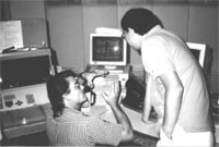
Local Console Allows Total Network Control Via Fiber Optic Cable Network
The local fiber network also connects to a statewide T3 backbone to allow the Project Operations Center in Sacramento to provide emergency back-up operations. This redundancy in project operations is a basic requirement according to Control System Engineer Larry Taber.
San Luis Power Plant houses eight turbines. The fiber optic network connects the controller for each turbine, through remote terminal units (RTUs), to the main control panel at the Area Control Center.
Remote Terminal Units
Each RTU requires four channels—one to receive satellite clock, one for the local intelligent man machine interface (IMMI), and one for each of the two front end processors (FEPs). (See Fiber Diagram #1).
The satellite clock is used for time stamping and synchronization. Clocking for synchronization delay times must be in tolerance of less than one second for local transmission and less than 30 seconds for remote.
The time stamping capability helps diagnose problems by allowing technicians to see the sequence of events between units. The IMMI interface is independent of the overall network and is used only for local control.
The FEPs are used for remote connections and are independent to the IMMI system. One of the FEPs connects directly into the intrastate T3 backbone, the other into an UNIX-based network.
The DWR installed a total of 32 channels at a maximum distance of about 600 feet. The fiber optic cable provided complete immunity to the electromagnetic (EMI) and radio frequency interference present in power plant environments. According to Ed Trevino, Senior Control System Engineer, “the power plant EMI had been corrupting the data.”
Peter Chan, DWR Telecommunications Engineer, first evaluated multidrop multiplexers but, after careful analysis, recommended the fiber solution from TC Communications, a fiber optic vendor specializing in process control and traffic management applications.
“We needed something small, inexpensive, flexible and reliable,” said Chan.
Specifically, the DWR opted to use two hardware devices from TC Communications in an innovative star configuration: the Model TC8916 Broadcast & Receive Device (BRD) and the TC8116 Fiber Optic Multiplexer (FOM) .
The star configuration also included redundancy in the form of dual fiber optic cable, dual power supplies and automatic switchover of either in the event of a failure. The four channels from each RTU were multiplexed over a duplex multimode fiber optic cable operating at the 850nm wavelength.
Broadcast & Receive Device
The Broadcast & Receive Device is essentially a modem sharing device that sends the incoming RS-232 signal in parallel to all remote locations. It “broadcasts” the outgoing signals in a polled sequence through the multiplexers to the RTUs. It sends a signal to multiple ports at the same time, but will receive only the port that is addressed. The BRD sends clock in one direction and the RS-232 signal in both directions.
Fiber Optic Multiplexer
The Fiber Optic Multiplexer is extremely compact and multiplexes up to 64 RS-232 ports. It can operate over single mode or multimode fiber and supports distances to approximately 20 km. It is expandable in increments of eight RS-232 ports. Each RS-232 channel supports data rates up to 19.2 Kbps via an RJ-11 connector.
Configuration flexibility is easily achieved by placing the BRD at the near and/or far end of the fiber link. Up to five units in any combination of FOM and BRD can be housed in a card cage (7"H X 11"D X 19"W) equipped with a redundant load sharing power supply.
Benefits
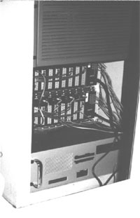
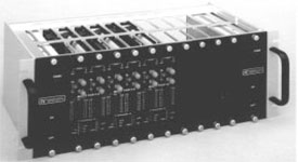
Rear View of Broadcast & Receive Device Located at the Control Center
The combination of the BRD and FOM provides the DWR with several important benefits:
- Independent cabling to each RTU enables problem isolation with a specific RTU
- Each RTU receives a polling request, recognizes its address, and responds accordingly to the FEP
- Improved network reliability with power and optical redundancy and automatic switchover
- Cost savings compared to using multidrop fiber multiplexers
- Can add additional channels to the network at any time
- Can reconfigure network at any time by moving the FOM and BRD around or adding new units
- Can use a variety of power sources—115/230 VAC, -48VDC, 12 VDC or a rack mount power card that automatically adjusts voltages between 85 and 260 VAC
SCADA
The TC Communications equipment also supports the real-time communications required for SCADA. The primary purpose of SCADA is to constantly monitor the condition of the network and identify and report any problems.
The SCADA system at San Luis is used to monitor a variety of important data including voltages, bearing temperatures, lube oil pressures/levels, brake oil pressures, etc. Abnormal conditions will trigger alarms at the local, central or remote monitoring sites.
The installation proceeded smoothly; however, installers paid special attention to port assignments, testing and cabling to help both immediate operations and future diagnostics. This "special attention" resulted in the following action items:
Connecting RJ-11 port #1 on the BRD to port #1 on the FOM, etc.
- Measuring each fiber link with a light source and power meter to establish a benchmark
- Cable modification to connect the RTU with the remote multiplexer such as RJ-45 connectors with DB-9 adapters to the RTU and RJ-11s for the FOM
- Using a “null modem cable” between the BRD and FOM
- DWR Control System Technician Robert Lewis noted an important factor when changing or upgrading a large control system similar to the San Luis Power Plant installation
“The new equipment usually cannot be installed at once,” Lewis commented. “This means that the communications system must be compatible with the old as well as with the new equipment during the transition which can also take months or even years before the new system cuts over.” It turned out that no problems were encountered with the TC Communications equipment.
Utility companies provide an ideal environment for advanced and imaginative uses of fiber optics. The San Luis Power Plant network, and other similar fiber optic networks, will undoubtedly benefit from these future advancements.
Broadcast & Receive Device
The TC8916 broadcasts and receives information from up to 16 remote devices. When the Host Polling Device sends information to the TC8916 via the RS-232 Host Port, it will broadcast to each of the 16 RS-232 user ports. The addressed remote device(s) will then respond back to the Host Device.
The TC8916 is transparent to all data sent in either direction. The TC8916’s RS-232 user ports can be remoted by either a single port fiber optic modem or the 8/16 channel Model TC8116 fiber optic multiplexer.
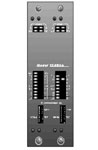
Front View of TC8916 Broadcast & Receive Device
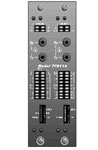
Front View of TC8116 Fiber Optic Mux
TC8116 Fiber Optic Multiplexer
Fiber Optic Multiplexer
Highly flexible, the Model TC8116 RS-232 Fiber Optic Multiplexer is frequently used in conjunction with the BRD. It offers a variety of options including rack mount or standalone, power redundancy (115/230VAC), interchangeable interfaces and single or multimode fiber optics.
Available in 16-channel modules, the TC8116 supports asynchronous and synchronous (external clock) data rates up to 38.4Kbps. Interfaces can be changed after installation. Each channel has Tx and Rx status LEDs and the unit provides Power and Sync LEDs.
The multimode versions are available 850 and 1300nm, single mode is 1300nm. Lost budgets are 15dBm for both versions.
SCADA
Supervisory Control and Data Acquisition (SCADA) systems are typically used in Utility Company environments to monitor remote terminal units (RTU). Applications typically interconnect the various vaults distribution substations and power elements that make up a particular network.
SCADA systems monitor a variety of plant data including temperatures, water levels voltages and pressure levels. Alarms at central or remote monitoring sites are triggered by any abnormal conditions.
The primary benefit of SCADA is to identify and correct problems quickly. By enabling constant monitoring of the condition of the network, it can often pinpoint problems for troubleshooting and maintenance technicians. It also helps reduce maintenance costs.
Configurations
Configures include star, bus, ring and counter-rotating ring. The star configuration, typically used in local applications, is particularly reliable because it provides independent fiber optic cables to each RTU.
The bus configuration is typically used for longer distances. It is vulnerable to power or optical failures since the signal cannot be repeated past the failure point. A single ring configuration is among the most economical; however, it also is vulnerable to failures.
The counter-rotating ring, often referred to as a selfhealing ring, is the best configuration in terms of reliability. TC Communication’s devices are designed to detect down stream failures and re-route the signals as required.